| This site uses cookies to enhance our services. By continuing to browse the site, you agree to our Cookies Policy. |
| This site uses cookies to enhance our services. By continuing to browse the site, you agree to our Cookies Policy. |
| CFD analysis about valve overlap period in the Wartsila 6L 46 four-stroke marine engine |
Wartsila 6L 46 has six cylinders in line, and every cylinder has two inlet and two exhaust valves. The valve follower is of the roller tappet type, where the roller profile is slightly convex for good load distribution. The valve mechanism includes rocker arms working on yokes guided by pins. The Wartsila 46 is provided with Spex (Single pipe exhaust) system and with high efficiency turbocharger. In the field of four-stroke marine engines, the Wartsila 6L 46 has become very popular on new cruise vessels, bulk carriers, cargo vessels, ferries, fishing boats, tankers, etc since it was launched onto the market in 1988. As the Wartsila 6L 46 is a non-reversing engine, in marine applications it is used as auxiliary engine (electric generator) or as main engine connected to a controllable pitch propeller.
Figure 1: Trasversal cut marine diesel engine Wärtsilä 46. Some examples of recent applications are the large Spain tuna
fish vessels “Albatún 2” and “Panama Tuna”. Other example is the chemical
tanker and the cruise vessel "Oasis of the Seas”.
 Figure 2: Engine room in Oasis of the Seas, with Wartsilla 46 as electric generator. Particularly, the valve timing events for the Wartsila
6L 46 are shown in the next Fig. As can be seen, the exhaust valves open 53º
before BDC and close 44º after TDC. On the other hand, the intake valves open
50º before TDC and close 26º after BDC. As can be seen, there is a period of
94º between the exhaust and intake strokes when the intake valves are opening and
the exhaust valves are closing, i.e., all valves are opened simultaneously. This
is called the valve overlap period.  Figure 4: Valves period in Wärtsilä 46. Valve overlap period, and is very important in large four-stroke diesel engines with high turbocharging because the expelling of the burnt gases by the fresh air is more efficient. The overlap period is also useful to refrigerate (the entering air at low temperature refrigerates the walls of the combustion chamber, piston head and exhaust valves. Besides, this air mixes with the burnt gases, which are directed to the turbocharger turbine. If these gases were too hot, the turbine blades would be damaged). For these reasons, the overlap period is very necessary. Unfortunately, the potential for mechanical or gas flow mayhem during the overlap period is obvious. If the cylinder and exhaust pressures are too high, large quantities of exhaust gas can be shuttled into the intake tract. This gas is hot, maybe 1000ºC, and can cause fuel residues on the back of the intake valves. Besides, if exhaust gas occupies the inlet conduct, only a fraction mass of air can be induced into the cylinder. If the air is not enough, the combustion is incomplete and the consequence is that an excess of unburned hydrocarbon emissions are expelled to the atmosphere. Hence, the design process of the engine during the valve overlap period is a very critical issue. In this regard, CFD is a very useful tool. The principle of operation of CFD codes is subdividing the domain into a number of smaller, non-overlapping subdomains. The result is a grid (or mesh) of cells (or elements). In this work, a grid generation program, Gambit 2.4.6, was used to generate the mesh. Due to the movement of the piston and valves, the domain changes into a new position of the calculation and the grid must be automatically reconstruct at each time step. The number of elements varies from 40000 at top dead center, to 500000 at bottom dead center. In order to minimize the number of cells and obtain good convergence, hexahedral elements were used to mesh the cylinder. Unfortunately, hexahedral elements do not adapt properly to the complex geometry of the valves and ducts, for this reason, tetrahedral elements were employed to the cylinder head and ducts. The cylinder head, especially around valves, was refined in order to capture the complex characteristics of the flow. 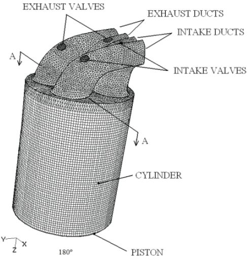 Figure 5: Mesh cylinder Wartsilla 46. At the beginning of the simulation, the pressure descends drastically due to the expansion of the piston. When the exhaust valves are opened, the in-cylinder pressure is slightly superior to the exhaust pressure, therefore burnt gasses are expelled through the exhaust ducts. When the intake valves are also opened, the in-cylinder pressure has an appropriate value, between the exhaust and intake pressures. Consequently, air enters through the intake ducts and burnt gases continue being expelled through the exhaust ducts. The velocity field overlaid with the pressure field. As initial conditions, the velocity inside the cylinder was imposed as the lineal velocity of the piston and it was assumed that the cylinder and exhaust ducts are full of burnt gases (red color), while the intake duct is full of air (blue color). When the exhaust valves are opened, high velocity burnt gases are expelled trough the exhaust ducts. A short time later, the inlet valves are opened and air enters through the intake ducts and burnt gases are expelled through the exhaust ducts. This process of entering fresh air and expelling burnt gases was verified during all the overlap period, i.e., between 310º and 404º. No retrocesión of burnt gases to the intake ducts was produced. This jeans that these operating conditions are adequate. Finally, at the end of the simulation, all valves are closed and residual velocities remain into the cylinder.  Figure 6: Results velocity field with CFD analysis In this work, numerical and experimental tests were performed over a commercial four-stroke marine engine, the Wartsila 6L 46. A CFD model has been used to simulate the exhaust, intake and compression strokes. Special attention was focused on the overlap valve period, which has a crucial influence on the performance of the engine. It was verified that the fluid flow during the overlap period is correct (no reverse flow was obtained). This work was validated, verifying measurements of the in-cylinder pressure. This model is an unprecedented opportunity for engineers to understand the highly complex flow interactions that occur in an engine, providing extra information which can not be analyzed with experimental techniques. Besides, this is a very useful tool do improve the performance of the new designs of engines because it is very easy and reasonably cheap to study the influence of parameters such as the exhaust and intake pressures, engine speed, cam profile design, etc. In order to obtain good results, it is necessary to make several meshes and ensure that the results are independent of the mesh.
COURSES RECOMMENDED: 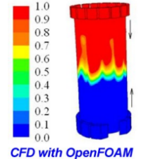 CFD with OpenFOAM online course CFD with OpenFOAM online courseLINKS: Wärtsilä, OpenFOAM, Polish Maritime Research |
| Published 2014-04-09 11:58:46 by Carlos Rodriguez & Isabel Lamas |
| Twittear |
 |